
 Residential fans
 Industrial fans
 Single-room air handling units with heat recovery
 Air handling units with heat recovery
 Air distribution
 Ducting
 Dampers
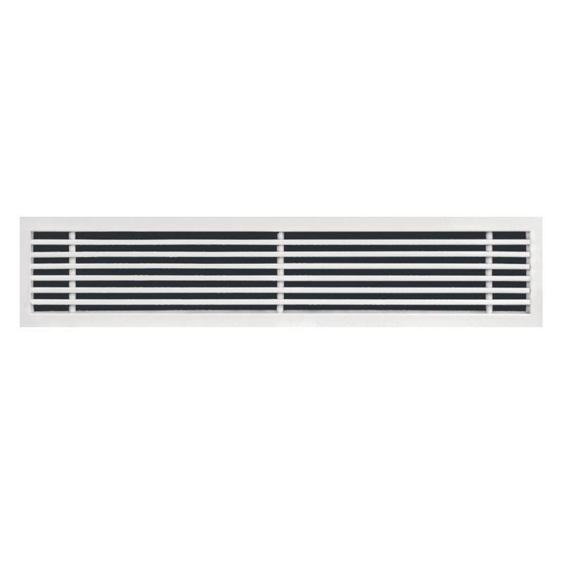
Blauberg Linear Bar Grilles

- Description
- Downloads
- Quick Selection Table
| FEATURES | |
|
All grilles, both with and without frames, can be manufactured with a hingeable access panel at one or both ends of the grille. The standard length of each panel piece is 150 mm, although this length can be varied upon request.Due to the large amount of possibilities offered by this type of grille, it is recommended to consult in specific vases with special dimensions. |
This range of grille has the necessary characteristics for its integration in contemporary architecture and interior design. They can be installed in ceilings, walls, consoles, fan-coils, induction units, both for supply and return air application and properly reinforced in floors.The maximum recommended length is 2 m in one piece, although 2 or more modules can be combined to give appearance of continuity. |
| DESIGN | GENERAL NOTES ON THE QUICK SELECTION TABLE |
|
Made of extruded aluminium.Fixed blades at 0 degree, 15 degree, 30 degree.Rigid, heavy gauge extruded frames with reinforced mitered and welded corners.Standard finish white, other finishes are available.Surface mounting or concealed mounting.Size manufactured on request.Construction is of a fixed core, while a hinged core option is available.
|
Apart from the before-mentioned factor Cs ( for grilles mounted in sill or floor ), another correction factor exists for the distance of the grille to the ceiling, when mounted in a wall. For a free jet this factor Ch will be 1.6.
Corrected throw = ThrowCh, with h in the graph the distance between grille and ceiling. Xc =×× Ch
|


| Flow rate | L | 1000 | 1000 | 1000 | 1000 | 1000 | 1000 | 1000 | 1000 | |
| H | 50 | 75 | 100 | 125 | 150 | 200 | 250 | 300 | ||
| (m³/h) | (l/s) | AK | 0.024 | 0.0370 | 0.0500 | 0.0630 | 0.0820 | 0.1080 | 0.1400 | 0.1720 |
| 100 | 27.8 | VK | 1.2 | 0.8 | 0.6 | |||||
| Х | 2.3 | 1.9 | 1.6 | |||||||
| Pt | 0.8 | 0.3 | 0.2 | |||||||
| NR | - | - | - | |||||||
| 120 | 33.3 | VK | 1.4 | 0.9 | 0.7 | |||||
| X | 2.8 | 2.2 | 1.9 | |||||||
| Pt | 1.1 | 0.5 | 0.3 | |||||||
| NR | - | - | - | |||||||
| 140 | 38.9 | VK | 1.6 | 1.1 | 0.8 | |||||
| X | 3.2 | 2.6 | 2.2 | |||||||
| Pt | 1.5 | 0.6 | 0.4 | |||||||
| NR | - | - | - | |||||||
| 160 | 44.4 | VK | 1.9 | 1.2 | 0.9 | |||||
| X | 3.7 | 3.0 | 2.6 | |||||||
| Pt | 2.0 | 0.8 | 0.5 | |||||||
| NR | - | - | - | |||||||
| 180 | 50.0 | VK | 2.1 | 1.4 | 1.0 | 0.8 | ||||
| X | 4.1 | 3.3 | 2.9 | 2.6 | ||||||
| Pt | 2.5 | 1.1 | 0.6 | 0.4 | ||||||
| NR | - | - | - | - | ||||||
| 200 | 55.6 | VK | 2.3 | 1.5 | 1.1 | 0.9 | ||||
| X | 4.6 | 3.7 | 3.2 | 2.8 | ||||||
| Pt | 3.1 | 1.3 | 0.7 | 0.5 | ||||||
| NR | 10 | - | - | - | ||||||
| 250 | 69.4 | VK | 2.9 | 1.9 | 1.4 | 1.1 | 0.8 | |||
| X | 5.8 | 4.6 | 4.0 | 3.6 | 3.1 | |||||
| Pt | 4.9 | 2.0 | 1.1 | 0.7 | 0.4 | |||||
| NR | 16 | 7 | - | - | - | |||||
| 300 | 83.3 | VK | 3.5 | 2.3 | 1.7 | 1.3 | 1.0 | 0.8 | 0.6 | |
| X | 6.9 | 5.6 | 4.8 | 4.3 | 3.7 | 3.3 | 2.9 | |||
| Pt | 7.0 | 2.9 | 1.6 | 1.0 | 0.6 | 0.3 | 0.2 | |||
| NR | 21 | 11 | - | - | - | - | - | |||
| 350 | 97.2 | VK | 4.1 | 2.6 | 1.9 | 1.5 | 1.2 | 0.9 | 0.7 | 0.6 |
| X | 8.1 | 6.5 | 5.6 | 5.0 | 4.4 | 3.8 | 3.3 | 3.0 | ||
| Pt | 9.5 | 4.0 | 2.2 | 1.4 | 0.8 | 0.5 | 0.3 | 0.2 | ||
| NR | 25 | 15 | 9 | - | - | - | - | - | ||
| 400 | 111.1 | VK | 4.6 | 3.0 | 2.2 | 1.8 | 1.4 | 1.0 | 0.8 | 0.6 |
| X | 9.2 | 7.4 | 6.4 | 5.7 | 5.0 | 4.3 | 3.8 | 3.4 | ||
| Pt | 12.4 | 5.2 | 2.9 | 1.8 | 1.1 | 0.6 | 0.4 | 0.2 | ||
| NR | 28 | 19 | 12 | 8 | - | - | - | - | ||
| 450 | 125.0 | VK | 5.2 | 3.4 | 2.5 | 2.0 | 1.5 | 1.2 | 0.9 | 0.7 |
| X | 10.4 | 8.3 | 7.2 | 6.4 | 5.6 | 4.9 | 4.3 | 3.9 | ||
| Pt | 15.7 | 6.6 | 3.6 | 2.3 | 1.3 | 0.8 | 0.5 | 0.3 | ||
| NR | 31 | 22 | 15 | 11 | 5 | - | - | - | ||
| 500 | 138.9 | VK | 5.8 | 3.8 | 2.8 | 2.2 | 1.7 | 1.3 | 1.0 | 0.8 |
| X | 11.5 | 9.3 | 8.0 | 7.1 | 6.2 | 5.4 | 4.8 | 4.3 | ||
| Pt | 19.4 | 8.2 | 4.5 | 2.8 | 1.7 | 1.0 | 0.6 | 0.4 | ||
| NR | 34 | 25 | 18 | 13 | 8 | - | - | - | ||
| 600 | 166.7 | VK | 6.9 | 4.5 | 3.3 | 2.6 | 2.0 | 1.5 | 1.2 | 1.0 |
| X | 13.8 | 11.1 | 9.6 | 8.5 | 7.5 | 6.5 | 5.7 | 5.2 | ||
| Pt | 28.0 | 11.8 | 6.4 | 4.1 | 2.4 | 1.4 | 0.8 | 0.5 | ||
| NR | 38 | 29 | 23 | 18 | 12 | 6 | - | - | ||
| 700 | 194.4 | VK | 8.1 | 5.3 | 3.9 | 3.1 | 2.4 | 1.8 | 1.4 | 1.1 |
| X | 16.1 | 13.0 | 11.2 | 9.9 | 8.7 | 7.6 | 6.7 | 6.0 | ||
| Pt | 38.1 | 16.0 | 8.8 | 5.5 | 3.3 | 1.9 | 1.1 | 0.7 | ||
| NR | 42 | 33 | 27 | 22 | 16 | 10 | 5 | - | ||
| 800 | 222.2 | VK | 9.3 | 6.0 | 4.4 | 3.5 | 2.7 | 2.1 | 1.6 | 1.3 |
| X | 18.4 | 14.8 | 12.8 | 11.4 | 10.0 | 8.7 | 7.6 | 6.9 | ||
| Pt | 49.7 | 20.9 | 11.5 | 7.2 | 4.3 | 2.5 | 1.5 | 1.0 | ||
| NR | 46 | 37 | 30 | 25 | 20 | 14 | 8 | - | ||
| 900 | 250.0 | VK | 6.8 | 5.0 | 4.0 | 3.0 | 2.3 | 1.8 | 1.5 | |
| X | 16.7 | 14.4 | 12.8 | 11.2 | 9.8 | 8.6 | 7.7 | |||
| Pt | 26.5 | 14.5 | 9.1 | 5.4 | 3.1 | 1.8 | 1.2 | |||
| NR | 40 | 33 | 28 | 23 | 17 | 11 | 7 | |||
| 1000 | 277.8 | VK | 7.5 | 5.6 | 4.4 | 3.4 | 2.6 | 2.0 | 1.6 | |
| X | 18.5 | 15.9 | 14.2 | 12.5 | 10.9 | 9.5 | 8.6 | |||
| Pt | 32.7 | 17.9 | 11.3 | 6.7 | 3.8 | 2.3 | 1.5 | |||
| NR | 42 | 36 | 31 | 25 | 20 | 14 | 10 | |||
| 1200 | 333.3 | VK | 6.7 | 5.3 | 4.1 | 3.1 | 2.4 | 1.9 | ||
| X | 19.1 | 17.1 | 14.9 | 13.0 | 11.4 | 10.3 | ||||
| Pt | 25.8 | 16.2 | 9.6 | 5.5 | 3.3 | 2.2 | ||||
| NR | 41 | 36 | 30 | 24 | 19 | 14 | ||||
| 1400 | 388.9 | VK | 6.2 | 4.7 | 3.6 | 2.8 | 2.3 | |||
| X | 19.9 | 17.4 | 15.2 | 13.3 | 12.0 | |||||
| Pt | 22.1 | 13.0 | 7.5 | 4.5 | 3.0 | |||||
| NR | 40 | 34 | 28 | 23 | 18 | |||||
SYMBOLS:AK – Effective areaVK – Effective velocity in m/sX – Throw in metres correspond to a terminal velocity in occupied zone of 0.25 m/sPressure (Pt) – All pressures are in Pa (N/m²)NR – Noise level index in dB based on a room absorption and one diffuser
