
 Residential fans
 Industrial fans
 Single-room air handling units with heat recovery
 Air handling units with heat recovery
 Air distribution
 Ducting
 Dampers
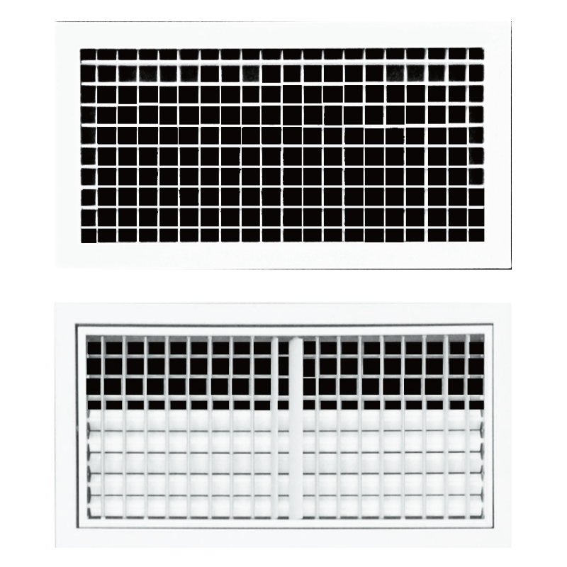
Blauberg Double Deflection Grilles

- Description
- Downloads
| FEATURES | |
|
For supply air, having a single set of fully adjustable blades to give directional control of the air pattern in four directions if required. Suitable for wall or duct mounting. Also available with curved face for circular duct installations. |
From extruded aluminium sections, ensuring functional strength and performance that also gives an attractive and aesthetically pleasing appearance. Incorporating two sets of individually adjustable blades, the blades may be set either horizontally or at angles, either up or down. Rear blades are adjusted in a similar way but only in a vertical plane. Powder coated white as standard with optional colors and finishes available on request. |
| DESIGN | |
|
Aluminium grilles, adjustable blades.Powder coated white as standard.H,L: Nominal ordering sizes (duct opening size).Designation: Vertical front blades & Horizontal front blade. |
Accessories: Sub frame SFR, Volume control damper, OBD, CLIP mounting clips for sub frame.Size manufactured on request.Blades are movable on horizontal and vertical lines. |
 |
|
 |
GENERAL NOTES ON THE QUICK SELECTION TABLE |
|
Some correction factors exist as a function of the ratio between room width and length, the blade deflection angle and the distance from grille to ceiling, and are defined in the following manner: A/L: Ratio between the width and the length of the room to be conditioned. For example, for a room with a width of 4.5 m and length of 4.5 m the factor A/L equals 1 (see fig 1).Ca: Factor obtained from the graph. For example, if the value of A/L = 1 and for a grille with 0° blade angle, the value of Ca equals 1.3 (see fig 2).Ch: Correction factor for height, obtained from the distance between grille and ceiling.For a free jet Ch is always 1.1.For example, if the grille is located at 0.2 m from the ceiling the factor Ch equals 1 (see fig 3&4).Once calculated, the correction factor for the throw (Kc) can be determined by the following formula: Kc = Ca × ChKc = 1.3 × 1 In this case of selection by table, we would obtain the correction throw (Xc): Xc = Kc × XXc = 1.3 × X
|
|
